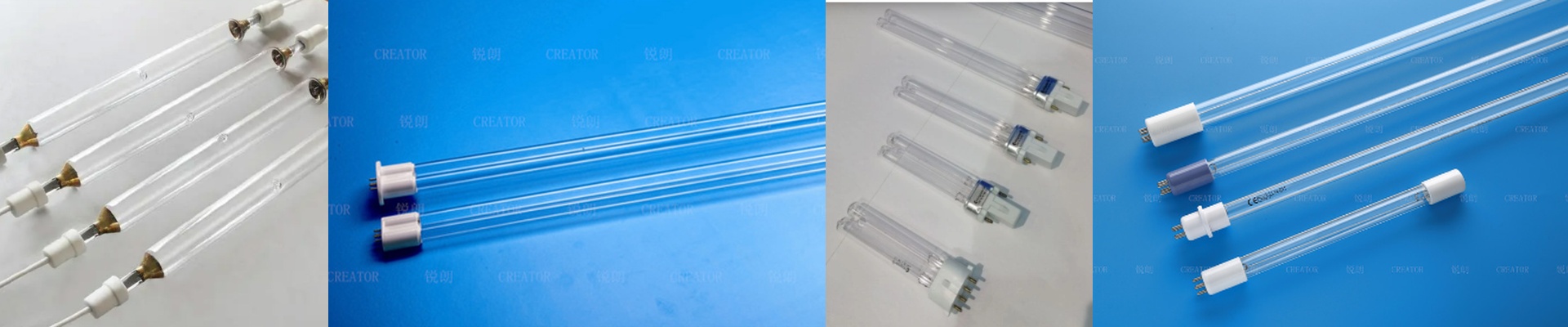
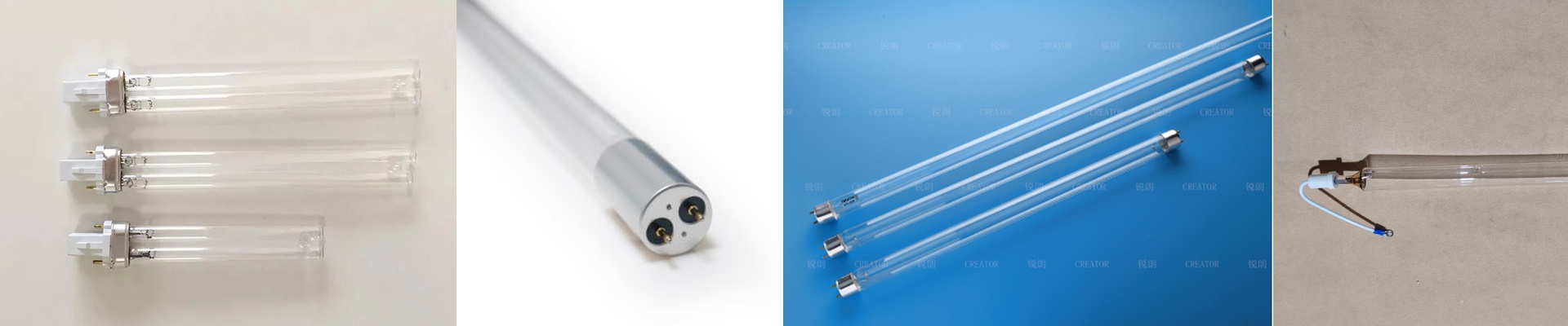
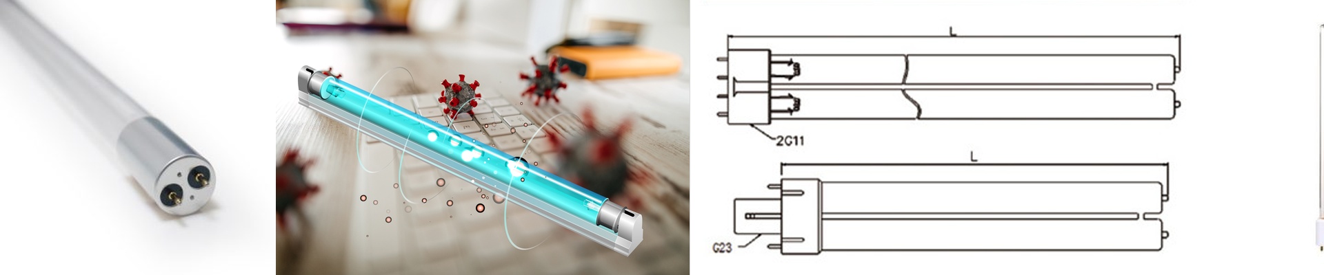
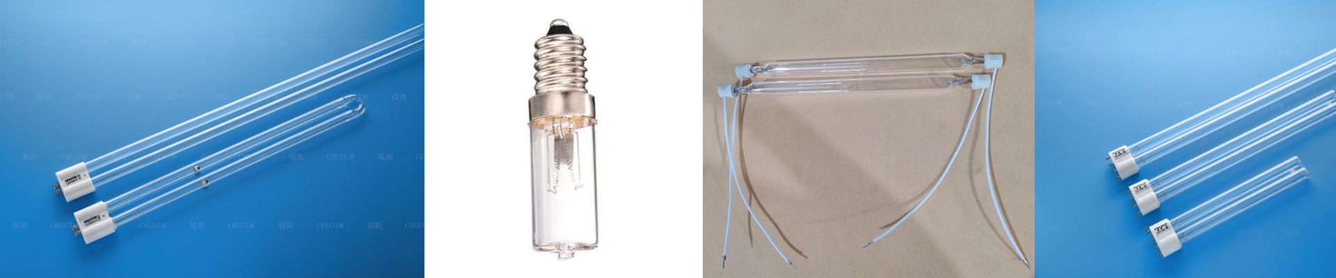
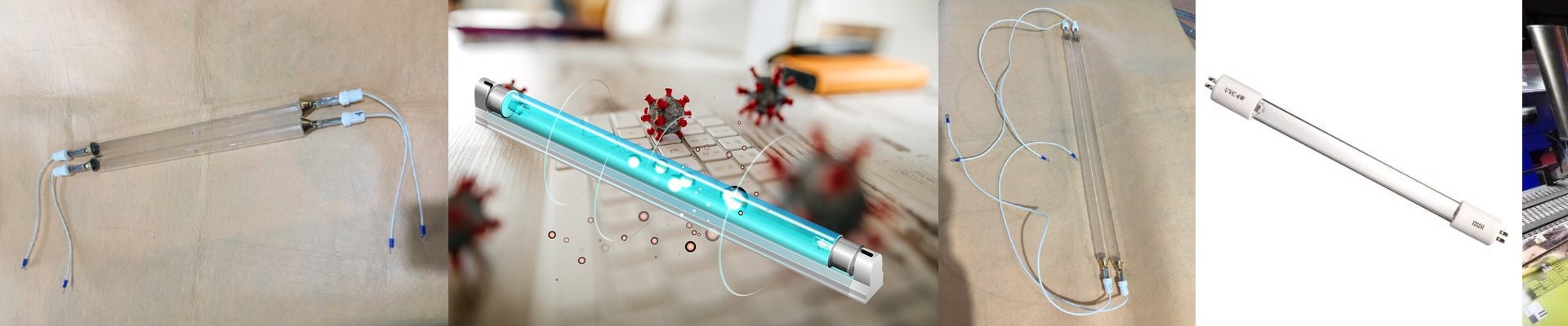
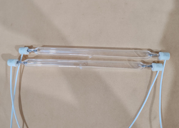
On a PCB line, you don’t get much margin. A single micron of under-cured solder mask between a 50-micron trace and its pad is the difference between making good boards and scrapping them. It’s not enough that the UV lamp lights up. What matters is whether it delivers the exact energy density needed to fully cross-link the photoinitiator in the resist. What matters under the hood We run a stabilized high-pressure mercury vapor discharge, tuned to put most of its punch at 365 nm. That wavelength sits right on the absorption peak of most solder mask initiators, so you get fast surface cure and through-cure without cooking the laminate. Peak irradiance hits 8 W/cm², and with our elliptical reflector and dichroic coating, you can deliver up to 5,000 mJ/cm² at the substrate plane. The payoff is a repeatable, measurable dose you can log with a spectral radiometer. Why this works in fine-line PCB work Tight spectral control keeps the photoinitiator from starving in the shadowed valleys between traces. The reflector concentrates the beam to hold uniformity across the board width, so you don’t fight the edge-to-center energy drop that causes brittleness and poor adhesion. In practice, that means faster curing cycles, fewer rejects, and adhesion you can count on even at line widths under 75 microns. What you need to get right on install and maintenance Match the lamp length and arc gap to the printer’s reflector geometry. Mismatched reflectors waste energy and chew up lamp life. This is high-voltage gear—handle it with ESD-safe procedures. The lamp is ozone-free, but keep the cooling airflow at the specified cubic feet per minute. If you don’t, thermal drift becomes a problem and the quartz envelope takes heat. Plan lamp replacement around the 2,000-hour mark. That’s how you keep the spectral output curve and irradiance stability where they need to be.